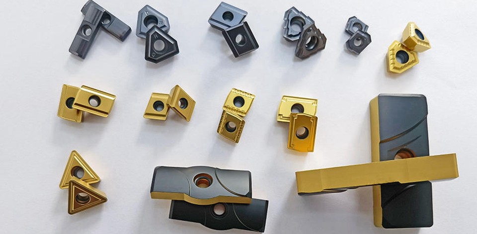
Carbide turning inserts chipbreaker
carbidedrilling Tools
Manufacturer of deep hole drilling tools and high quality carbide cutting tools,If you want to find a good quality and reliable supplier of carbide inserts, find us. If you want just cheapest price, then we are sorry.
Selection of chip breaking groove shape of turning tool
(1) Curling and breaking of chips
1. Chip outflow direction and chip flow angle φλ
The chip flow direction has an important influence on chip curling and breaking. The angle between the flow direction and the normal plane of the main edge is called the chip flow angle φλ, as shown in Figure 3-30. Due to many factors affecting the direction of chip flow, it is not yet possible to accurately predict the size of the chip flow angle. During right-angle free cutting, chips flow out along the vertical direction of the cutting edge, and the chip flow angle φλ≈0. When the bevel angle is free cutting (such as a wide-edged fine planer installed obliquely), the chip flow angle is approximately equal to the inclination angle of the working edge (φλ=λse). For general cutting, in addition to the main cutting edge, it is also affected by the secondary cutting edge. In general, the principle that chips flow out along the direction with the least energy consumption exists. Since the material at the root of the cutting zone is in a plastic state, small changes in the force acting on the chips will affect the flow direction of the chips. For example, the direction of the chip breaker, the obstacle of the workpiece, the geometric parameters of the tool, the wear of the tool, the built-up edge, the unevenness of the cutting amount and the material of the workpiece, etc., and even the length of the chip itself affects the direction of the outflow of the chip. The flow direction of chips is not only an important problem in the study of cutting mechanism, but also directly related to the control of chips. If the action direction of the chip breaker is not perpendicular to the chip flow direction, it will affect its chip breaking effect.
2. Curl of chips
The chip is accompanied by curling during the outflow process, and the flow direction and curling of the chip determine the shape of the chip. When the chip curls upwards only along the chip thickness direction, the curling axis of the chip is parallel to the bottom surface of the chip, and the angle between them is θ = 0°. With the difference of the chip flow angle φλ, the chip shape formed is also different. It can be seen from Fig. 3-30 that when φλ=0°, there is no lateral flow of chips, and flat disc-shaped spiral chips (spring-shaped chips) are formed. When φλ≠0°, the chip curls upward while moving along its curling axis, that is, the chip moves in a spiral. When the value of φλ is large, if the moving distance of the chips is greater than or equal to the nominal width of the cutting layer while the chips are turning a circle, tubular spiral chips will be formed; if the value of φλ is small, the chips will move less along the curling axis, which is easy to form Cone-disk spiral chips (pagoda-shaped chips).
When the chips only have lateral (side) curls but no upward curls, the curling axis of the chips is perpendicular to the bottom surface of the chips (θ=90°), forming a ring-shaped spiral chip like a gasket.
When the chips have both upward curl and side curl, the chip outflow angle φλ is not zero, and ring or conical spiral chips can be generated depending on the size of each parameter. When the upward or lateral curl of the chips is small, long strips or irregular banded chips are formed. If a chip breaker is made in front of the tool, the chips that flow out after the basic deformation (the deformation of the first and second deformation zones) can be curled again—additional deformation, making the chips harder and more brittle and easier to break. Therefore, curling and breaking of chips are closely related.
The radius of curvature rDX of the chips curling up is related to the parameters of the chip breaker. Taking the linear arc-shaped chipbreaker as an example, when the bottom surface of the chip is in contact with the shoulder of the chipbreaker, it is shown in Figure 3-31. The average radius of curvature rDX of chips curled in the chipbreaker can be calculated from the geometric relationship:
In the formula
Wn——Width of chip breaker (mm);
hn — depth of chip breaker (mm);
hDX——chip thickness (mm);
lf ——The contact length between chips and the front, when cutting steel, lf ≈ hDX (mm).
(2) Chipbreaker geometry and parameters
1. Chipbreaker geometry
The chip breakers of welded turning tools are ground when the tool is sharpened, while indexable turning tools are directly pressed into shape during the production of inserts.
(1) Chipbreaker truncated. The cross-sectional shape and size of the chipbreaker have an important influence on the chip breaking performance and cutting efficiency. The basic sectional shapes include straight-line circular arc, broken line, and full circular arc.
Linear arc-shaped chip breaker: This section is composed of straight lines and general arcs. The front of the turning tool is composed of a plane part close to the cutting edge. The basic parameters of the chip breaker are: width Wn=1~7mm, arc Radius Rn=(0.4~0.7)Wn, wedge angle βo≤40, negative chamfer width bn ≤fo, Rn and Wn are the main factors affecting chip shape, and the size of Rn directly affects chip curl radius.
Figure 3-32 Basic sectional shape of the chipbreaker
Broken-line chipbreaker: It is formed by the intersection of two straight lines. The groove bottom angle θ replaces the function of the arc radius Rn described above. When the value is small, the curling radius of the chip is small. If the value of θ is too small, the chip will be blocked in the groove, which is easy to cause the knife to be hit; if the value of θ is too large, the curling radius of the chip will be increased and it will not be easy to break. The groove angle is generally recommended to be 110° ~ 120°.
Full-arc chipbreaker: Under the same rake angle and groove width, the full-arc chipbreaker has higher cutting edge strength, so it is suitable for larger rake angle and heavy-duty turning tools. There is the following approximate relationship between the truncated groove width Wn, arc radius Rn and rake angle γo:
(2) Chipbreaker flute bevel. The bevel angle of the chipbreaker flute refers to the inclination angle of the chipbreaker relative to the main cutting edge. There are three forms, as shown in Figure 3-33.
Figure 3-33 Commonly used chipbreaker flutes
A-shape: This groove shape is characterized by front and rear equal width and equal depth open half grooves, which is called parallel type. This groove shape can still obtain better chip breaking effect in the case of a wide variation range of ap. However, for an insert with a certain groove width, the chip breaking range is narrow, and the groove width should be determined according to the feed rate.
Y shape: It is characterized by an open half groove with a wide front and a narrow rear, also known as an outward slope. The cutting speed of this groove shape A is high, the groove width is narrow, and the groove depth is small. The chips are curled here first, and the curl radius is small. At point B of the groove, the chips curl slowly, and the groove depth is large, and the bottom of the groove forms a negative edge inclination, which makes the chips easy to collide with the surface of the workpiece to form arc-shaped chips. When this kind of flute is used for medium back cutting ap, chip breaking is stable and reliable. When the ap is large, because the difference between the curling radii of A and B is too large, chips are easy to block.
K shape: The groove shape is an open half groove with a narrow front and a wide rear, also known as an inner slope. Contrary to the Y shape, the groove at B is narrow in width and small in depth, and the bottom of the groove has a positive edge inclination, so the chips are easy to flow away from the workpiece, forming tubular or ring-shaped spiral chips. Its chip breaking range is narrow, and it is mainly suitable for small cutting amount, finish turning and semi-finish turning, and it is also often used to guide chips to flow out of the hole during hole machining.
2. Selection of Chipbreaker Parameters
(1) Cutting carbon steel. Under the condition of medium engagement and feed rate (ap=1~6mm, f=0.2~0.6mm/r), when cutting medium carbon steel with cemented carbide turning tool, if it is required to form C-shaped chips, it is recommended to use straight line For arc-shaped chip breaker, take arc radius Rn=(0.4~0.7)Wn, select outer inclined type τ=8°~10°, or choose parallel type, the width Wn of chip breaker is selected to be equal to or slightly larger than the specified The maximum ap value adopted, the feed range is about f=Wn/10~Wn/14.
When the cutting depth is small (ap<1mm), if the above-mentioned chip breaker is used, it is not easy to break the chip. Because the chip breaker is too wide, the chips turn to the main cutting edge and flow out near the tool tip without passing through the bottom of the groove under the action of the arc of the tool tip and the minor cutting edge, and no additional curling deformation can be obtained. For this reason, the selected chip breaking groove shape and parameters must force the chip to curl or deform in the groove before it turns around the tool tip. As shown in Figure 3-34, the D-shaped chipbreaker can be used at this time, and it can be sharpened into a 45° oblique groove; the linear arc-shaped A-shaped chipbreaker can also be selected. When f=0.1mm/r, Desirable Wn=3f, hn=f, Rn=f/2.
Under the conditions of large cutting capacity and large feed rate (ap>10mm, f=0.6 ~ 1.2mm/r), due to the wide and thick chips, if C-shaped chips are formed, the cutting edge will be easily damaged, and the chips will splash and hurt people . Usually a full circular arc chip breaker is used and the arc radius Rn is increased to reduce the groove depth, so that the chips are rolled into a spring and broken on the transition surface, or fall by their own weight. According to the experience of processing large parts, the chipbreaker recommends the following parameters: groove width Wn=10f, arc radius Rn=(1.2~1.5)Wn; choose parallel or outward slope: τ=0°~6°. For the upward pressure indexable turning tool (see Figure 3-24), when the chip breaker is formed by the pressure plate, the bottom angle of the groove is θ=125°~135°.
Figure 3-34 45° oblique groove and chip breaking range of small back cutting
Due to the large deformation of low-carbon steel chips, the chip thickness hDX is thicker than that of medium-carbon steel under the same conditions, so it is easy to break chips. Cutting practice has proved that with the same chip breaker parameters, the chip breaking range of low carbon steel is wider than that of medium carbon steel. Therefore, the same chipbreaker parameters as cutting medium carbon steel can be used when cutting low carbon steel.
(2) Cutting alloy steel. Generally speaking, the strength and toughness of alloy steel are improved to varying degrees compared with medium carbon steel, which increases the difficulty of chip breaking, so it is necessary to increase the additional deformation appropriately. Such as cutting 18CrMnTi, 38CrMoAl, 38CrSi and other alloy steels, it is recommended to use the outer inclined chip breaker, and the groove width Wn and arc radius Rn should be appropriately reduced.
(3) Cutting difficult chip breaking materials. In metal cutting, some metal materials that are particularly difficult to break chips are often encountered, such as high-temperature alloys, high-strength steels, wear-resistant steels and stainless steels, as well as pure copper, oxygen-free copper, pure iron, etc. If the above-mentioned chip breaker is used, if the chip break is still not smooth, the shape of the main cutting edge can be changed, and a special chip breaker, vibration chip breaker, etc. can be used to achieve the purpose of chip breaking. For example, for the pure copper and oxygen-free copper chip breaking turning tools used in production, multiple arc-shaped grooves are ground on the back of the turning tool to make the main cutting edge into a corrugated washboard shape (rear washboard turning tool). Figure 3-55 shows a double-edge inclination cutting edge, that is, a second edge inclination is ground on the main cutting edge near the tip. The double-edge inclination can be used in conjunction with the ordinary outwardly inclined chipbreaker, the groove width Wn = 3.5~5mm, the outer bevel τ=6°~8°, the first edge inclination λs1=-3°, the second edge inclination λs2 =-(20°~25°), length Lλs2=ap/3. It is suitable for rough machining of stainless steel and has better chip breaking effect. The optimal range of cutting amount is: ap=4~15mm, f=0.1~0.35mm/r, vc=80~100㎡/min. This kind of turning tool has good tip strength, large chip curling radius, and most of them form conical disc-shaped spiral chips (pagoda chips) or short tubular spiral chips, but the radial force is 20% to 30% larger than that of single-edge inclination turning tools. It should not be used when the stiffness of the process system is poor.